Top 3 Cable Tracing Technologies
Firstly, why would you need to trace network cabling? In a perfect world you wouldn’t need to, but even if a network begins life properly labelled, things have a habit of changing. Documentation and cable labelling don’t always keep up when changes are made.
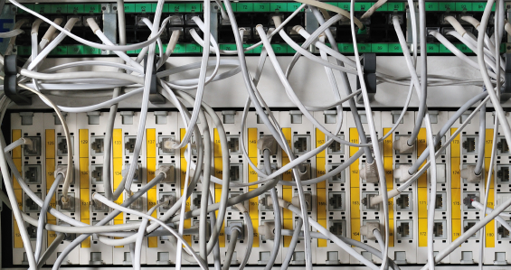
A jumble of network cables in a network cabinet.
When you need to re-arrange the cabling in your patch panel, can you be 100% certain that the label is correct? You can be reasonably certain if you installed and maintain the network yourself, but what if others are involved. Are they as fastidious as you are in keeping the network documentation up to date?
Before cable moves, it doesn’t do any harm to make sure the label is up to date. It is one thing to disconnect a single phone or workstation, quite another to disconnect the server.
A number of different technologies exist for tracing network cabling. Each technology has their plus points and their down sides too. A brief explanation of each technology will now follow outlining when each should be applied.
Tone Tracing
Tone tracing is pretty much as old as copper cabling itself. Tone tracing is the grand daddy of all cable tracer technologies. The basic idea is that at one end of the cable you place an electrical signal onto the cable, using a tone generator, and then trace that signal, using a tone tracer, in order to understand where the cable is located.
It could not really be much simpler. Well unfortunately, it is simple in theory, and usually it really is that simple in practice, but there are some things in network cabling especially that manage to make things a little more complex.
The design characteristics of the network cable are working against you. The design of Unshielded Twisted Pair (UTP) cabling is meant to reduce the interference between the pairs of copper wire that make up the cable as a whole. All of CAT5, CAT5e, CAT6 cable types have four pairs of copper wire carefully twisted together to minimise interference. This presents a number of problems to anyone attempting to trace a category 5, 5e or 6 cable because you wish to maximise the signal on the cable in order to increase the strength of the signal you can detect.
The best way to minimise the effective damping effect of the cable twists is to place the signal on a single wire within the cable whilst the other pair is earthed. If a signal is placed onto both pairs in a cable the twists in the cable will work to dampen the signal, placing the signal onto a single wire will help to avoid the dampening effect.
Tone tracers have traditionally been analog. More recently digital or asymmetric tone tracers have arrived onto the market. Asymmetric toners have a number of advantages over more traditional analog tracers.
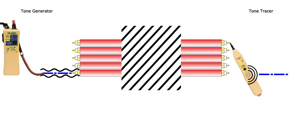
A diagram showing how a tone generator and tone tracer works.
Tone tracing provides the only cable tracing technology that can be performed on a live cable. More modern asymmetric tone tracers operate at frequencies well above the level that even very modern cable like CAT7 operate. Consequently, the tone signal does not interfere with the network signal.
Locating exactly where the fault lies can be very useful in deciding whether a cable run needs replacing or repairing. A fault close to the end of the cable may be repairable. Conversely, a fault in the middle of the cable would, in all likelihood, require a replacement. A tone tracer can be used to locate a fault, though it is a laborious process tracing each wire until the break is located. A full featured cable tester or TDR tester would be much faster and consequently a much better use of your time.
Continuity Testing
A continuity tester provides the ideal way to locate and label your network cabling. Whilst a toner can only work one cable at a time, a continuity tester can locate up to 20 cables at a time.
Each continuity tester is supplied with at least one remote. The remote fixes onto one end of your cable and you place the tester itself on the other end. When the tester and the remote are connected to the same cable, the continuity tester will show the number of the connected remote. Additional remotes can usually be supplied for most continuity testers or are included in the kit form of the tester. The additional remotes are numbered sequentially allowing you to locate and label a batch of cables at a time. If you have a large number of cables to locate, this can be a real time saver and will save you a lot of leg work.
In addition, a continuity tester is also capable of simple cable testing ensuring that all of the pairs of wires have no breaks and are connected correctly. It must be stressed that low end continuity testers can be fooled into giving a positive result when the cable is incorrectly wired.
Most continuity testers have a tone generator built in, so, with the addition of a tone tracer, can be used for tone tracing as well. Using the built in tone generator on a continuity tester can save you from carrying around a tool, saving you space and weight in your kit bag.
Hub Blink
Most modern hubs and switches have activity lights for each port indicating the traffic level and status. A recent addition to many cable testers and outlet identifiers has been the ability to blink the lights on a port. This feature is called hub blink.
Of course, this feature is only useful if the cables you wish to locate are connected to a live network. Hub blink is completely useless if you are trying to locate bare wire cables or before the network infrastructure has been installed.
Conclusion
Which technology you find a best fit is largely dictated by a few factors like how many cables you need to track and whether the cables are live.
If you are tracking cables that are not terminated, your options are traditional tone generator and tracer or continuity tester. Ditto if the cable is live, your only option is to use an asymmetric toner.
Hub blinking is also fine so long as your switch is relatively small. If you’ve got a huge switch with hundreds of ports, you may well struggle to identify exactly which port is blinking.
If you have a lot of cables to find, then a continuity tester with multiple remotes will allow you to identify cables in batches, speeding up the process of identification and labelling.